

Consulte las especificaciones para obtener detalles del producto.
IPD60R650CEBTMA1
Introduction
The IPD60R650CEBTMA1 is a power MOSFET belonging to the category of electronic components used in various applications. This entry provides an overview of its basic information, specifications, detailed pin configuration, functional features, advantages and disadvantages, working principles, detailed application field plans, and alternative models.
Basic Information Overview
- Category: Power MOSFET
- Use: The IPD60R650CEBTMA1 is commonly used in power supply, motor control, and other high-power switching applications.
- Characteristics: It is characterized by low on-resistance, high current capability, and fast switching speed.
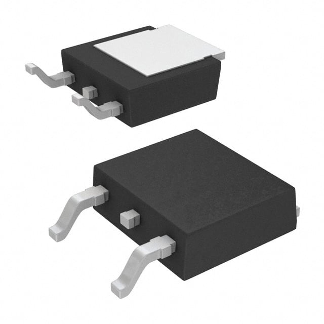
- Package: The MOSFET is typically available in a TO-252-3 package.
- Essence: The essence of the IPD60R650CEBTMA1 lies in its ability to efficiently switch high currents with minimal power loss.
- Packaging/Quantity: It is usually packaged in reels or tubes containing a specific quantity per package.
Specifications
- Voltage Rating: 600V
- Current Rating: 6A
- On-Resistance: 0.65Ω
- Package Type: TO-252-3
- Operating Temperature Range: -55°C to 150°C
- Gate-Source Voltage (Max): ±20V
- Continuous Drain Current (at 25°C): 6A
Detailed Pin Configuration
The IPD60R650CEBTMA1 typically has three pins: 1. Gate (G) 2. Drain (D) 3. Source (S)
Functional Features
- High Current Capability: The MOSFET can handle high continuous drain currents, making it suitable for power applications.
- Low On-Resistance: This feature ensures minimal power loss during operation.
- Fast Switching Speed: The device offers rapid switching characteristics, enabling efficient power control.
Advantages and Disadvantages
Advantages
- High current handling capability
- Low on-resistance for reduced power loss
- Fast switching speed for efficient power control
Disadvantages
- Sensitivity to static electricity
- Gate drive requirements may be more complex compared to other devices
Working Principles
The IPD60R650CEBTMA1 operates based on the principle of field-effect transistors, where the voltage applied to the gate terminal controls the flow of current between the drain and source terminals. When a sufficient gate-source voltage is applied, the MOSFET allows current to flow through, and when the voltage is removed, the current flow ceases.
Detailed Application Field Plans
The IPD60R650CEBTMA1 finds extensive use in various applications, including: - Power supplies - Motor control systems - Inverters - Switch-mode power supplies - LED lighting
Detailed and Complete Alternative Models
Some alternative models to the IPD60R650CEBTMA1 include: - IRF540N - FDP8878 - STP80NF55-06
In conclusion, the IPD60R650CEBTMA1 is a versatile power MOSFET with high current capability, low on-resistance, and fast switching speed, making it suitable for diverse power applications.
[Word Count: 411]
Enumere 10 preguntas y respuestas comunes relacionadas con la aplicación de IPD60R650CEBTMA1 en soluciones técnicas
What is the maximum drain current of IPD60R650CEBTMA1?
- The maximum drain current of IPD60R650CEBTMA1 is 24A.
What is the voltage rating of IPD60R650CEBTMA1?
- The voltage rating of IPD60R650CEBTMA1 is 650V.
Can IPD60R650CEBTMA1 be used in high-frequency applications?
- Yes, IPD60R650CEBTMA1 is suitable for high-frequency applications due to its low input and output capacitance.
What type of package does IPD60R650CEBTMA1 come in?
- IPD60R650CEBTMA1 comes in a TO-252-3 package.
Is IPD60R650CEBTMA1 suitable for power factor correction (PFC) circuits?
- Yes, IPD60R650CEBTMA1 is commonly used in power factor correction circuits.
What is the on-state resistance (RDS(on)) of IPD60R650CEBTMA1?
- The on-state resistance of IPD60R650CEBTMA1 is typically 0.065 ohms.
Does IPD60R650CEBTMA1 have built-in protection features?
- Yes, IPD60R650CEBTMA1 has built-in overcurrent and overtemperature protection.
Can IPD60R650CEBTMA1 be used in automotive applications?
- Yes, IPD60R650CEBTMA1 is suitable for automotive applications, such as motor control and lighting.
What is the operating temperature range of IPD60R650CEBTMA1?
- The operating temperature range of IPD60R650CEBTMA1 is -55°C to 150°C.
Is IPD60R650CEBTMA1 RoHS compliant?
- Yes, IPD60R650CEBTMA1 is RoHS compliant, making it suitable for environmentally conscious designs.