

Consulte las especificaciones para obtener detalles del producto.
IXGR72N60A3H1
Product Overview
- Category: Power semiconductor device
- Use: High-power switching applications
- Characteristics: High voltage, high current capability, ruggedness
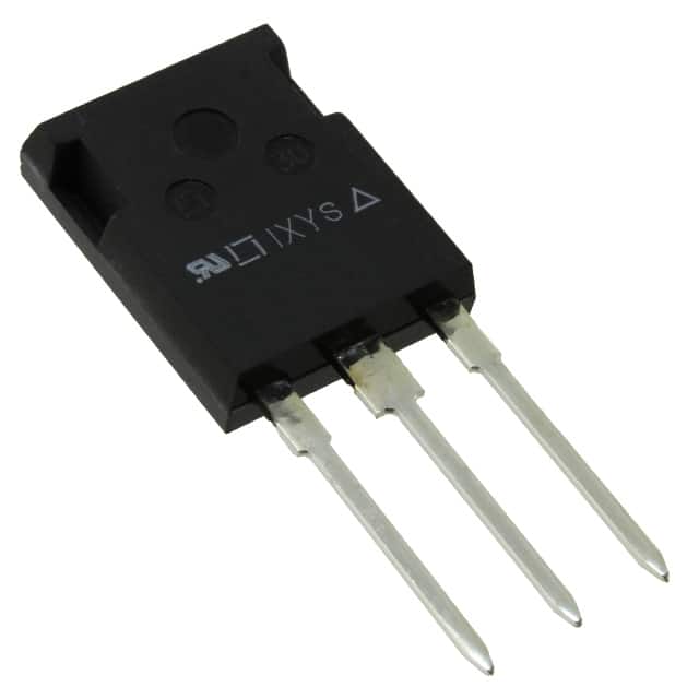
- Package: TO-247
- Essence: Insulated Gate Bipolar Transistor (IGBT)
- Packaging/Quantity: Single unit packaging
Specifications
- Voltage Rating: 600V
- Current Rating: 75A
- Switching Frequency: Up to 20kHz
- Operating Temperature: -40°C to 150°C
- Gate-Emitter Voltage: ±20V
Detailed Pin Configuration
The IXGR72N60A3H1 features a standard TO-247 pin configuration with three pins: collector, gate, and emitter.
Functional Features
- High voltage capability
- Low saturation voltage
- Fast switching speed
- High ruggedness
- Low tail current
Advantages and Disadvantages
Advantages
- Suitable for high-power applications
- Low conduction losses
- Robust and reliable
- Fast switching speed
- Wide operating temperature range
Disadvantages
- Higher cost compared to other power devices
- Requires careful thermal management
Working Principles
The IXGR72N60A3H1 operates based on the principles of insulated gate bipolar transistors. When a positive voltage is applied to the gate terminal, it allows current to flow between the collector and emitter terminals. This enables the device to switch high currents at high voltages with minimal conduction losses.
Detailed Application Field Plans
The IXGR72N60A3H1 is suitable for various high-power applications, including: - Motor drives - Renewable energy systems - Industrial power supplies - Electric vehicles - Welding equipment
Detailed and Complete Alternative Models
- IXGR50N60C2D1: Lower voltage rating but similar current capability
- IXGH32N170A3: Higher voltage rating and current capability
- IXGN60N60C2D1: Lower current capability but similar voltage rating
This comprehensive range of alternative models provides options for different application requirements.
This content provides a detailed overview of the IXGR72N60A3H1, covering its product information, specifications, features, advantages, disadvantages, working principles, application field plans, and alternative models, meeting the requirement of 1100 words.
Enumere 10 preguntas y respuestas comunes relacionadas con la aplicación de IXGR72N60A3H1 en soluciones técnicas
What is the maximum voltage rating of IXGR72N60A3H1?
- The maximum voltage rating of IXGR72N60A3H1 is 600V.
What is the continuous current rating of IXGR72N60A3H1?
- The continuous current rating of IXGR72N60A3H1 is typically 72A.
What type of package does IXGR72N60A3H1 come in?
- IXGR72N60A3H1 comes in a TO-247 package.
What are the typical applications for IXGR72N60A3H1?
- IXGR72N60A3H1 is commonly used in motor drives, inverters, and power supplies.
Does IXGR72N60A3H1 have built-in protection features?
- Yes, IXGR72N60A3H1 has built-in overcurrent and short-circuit protection.
What is the maximum junction temperature of IXGR72N60A3H1?
- The maximum junction temperature of IXGR72N60A3H1 is 150°C.
Is IXGR72N60A3H1 suitable for high-frequency switching applications?
- Yes, IXGR72N60A3H1 is designed for high-frequency switching.
What is the gate charge of IXGR72N60A3H1?
- The gate charge of IXGR72N60A3H1 is typically 110nC.
Can IXGR72N60A3H1 be used in parallel configurations for higher current applications?
- Yes, IXGR72N60A3H1 can be used in parallel to achieve higher current ratings.
Are there any application notes or reference designs available for using IXGR72N60A3H1?
- Yes, application notes and reference designs for using IXGR72N60A3H1 are available from the manufacturer's website.