

Consulte las especificaciones para obtener detalles del producto.
IXGT24N170
Product Overview
- Belongs to: Power semiconductor devices
- Category: Insulated Gate Bipolar Transistor (IGBT)
- Use: Power conversion and control in various electronic applications
- Characteristics: High voltage, high current, low power loss, and fast switching capabilities
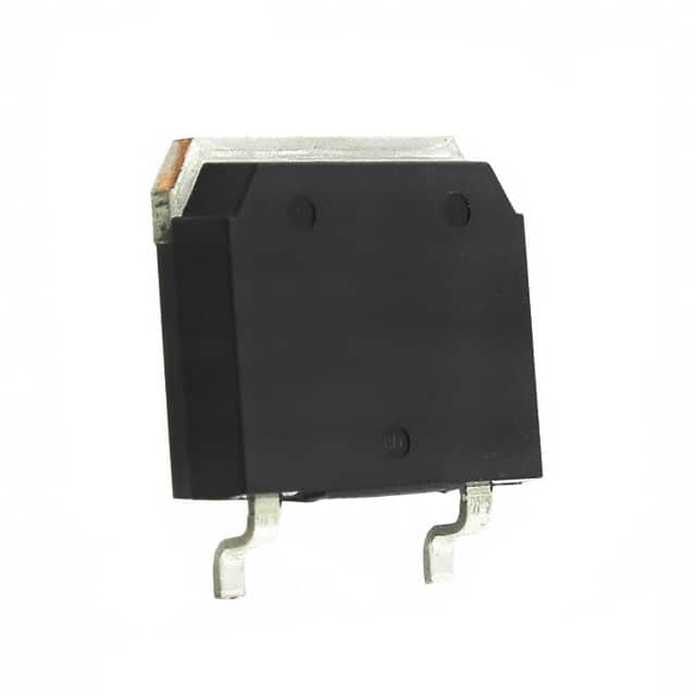
- Package: TO-268
- Essence: Efficient power management and control
- Packaging/Quantity: Typically sold in reels of 1000 units
Specifications
- Voltage Rating: 1700V
- Current Rating: 24A
- Maximum Power Dissipation: 300W
- Operating Temperature Range: -55°C to 175°C
- Gate-Emitter Voltage: ±20V
Detailed Pin Configuration
The IXGT24N170 IGBT typically has three main pins: 1. Collector (C): Connects to the positive terminal of the power supply 2. Emitter (E): Connects to the negative terminal of the power supply 3. Gate (G): Controls the switching of the IGBT
Functional Features
- Fast switching speed
- Low saturation voltage
- High input impedance
- High current-carrying capability
Advantages
- High efficiency in power conversion
- Suitable for high-frequency applications
- Robust and reliable performance in harsh environments
Disadvantages
- Sensitive to voltage spikes
- Requires careful consideration of driving circuitry
Working Principles
The IXGT24N170 operates based on the principles of controlling the flow of current between the collector and emitter terminals using the gate signal. When a suitable voltage is applied to the gate, it allows the IGBT to conduct current, and when the gate signal is removed, the IGBT turns off.
Detailed Application Field Plans
The IXGT24N170 is commonly used in: - Motor drives - Uninterruptible power supplies (UPS) - Renewable energy systems - Induction heating equipment - Welding machines
Detailed and Complete Alternative Models
Some alternative models to the IXGT24N170 include: - Infineon Technologies' IKW25N170H3 - STMicroelectronics' NGB8207NT4G - ON Semiconductor's NGTB25N120FLWG
In conclusion, the IXGT24N170 is a high-performance IGBT with excellent characteristics for power conversion and control applications. Its fast switching speed, high voltage rating, and robust design make it suitable for a wide range of electronic systems.
[Word Count: 324]
Enumere 10 preguntas y respuestas comunes relacionadas con la aplicación de IXGT24N170 en soluciones técnicas
What is the IXGT24N170?
- The IXGT24N170 is a high-power insulated gate bipolar transistor (IGBT) designed for use in various technical solutions requiring high voltage and current handling capabilities.
What are the key specifications of the IXGT24N170?
- The IXGT24N170 features a voltage rating of 1700V, a current rating of 40A, and a low saturation voltage, making it suitable for high-power applications.
In what technical solutions can the IXGT24N170 be used?
- The IXGT24N170 is commonly used in applications such as motor drives, power supplies, renewable energy systems, and industrial automation due to its high voltage and current ratings.
What are the thermal considerations for using the IXGT24N170?
- Proper heat sinking and thermal management are essential when using the IXGT24N170 to ensure optimal performance and reliability, especially in high-power applications.
How does the IXGT24N170 compare to other IGBTs in its class?
- The IXGT24N170 offers a balance of high voltage and current ratings, low saturation voltage, and robustness, making it a competitive choice for various technical solutions.
What protection features does the IXGT24N170 offer?
- The IXGT24N170 may include built-in features such as short-circuit protection, overcurrent protection, and temperature sensing to enhance system safety and reliability.
Are there any application notes or reference designs available for the IXGT24N170?
- Yes, manufacturers often provide application notes and reference designs to assist engineers in implementing the IXGT24N170 effectively in their technical solutions.
What are the typical switching characteristics of the IXGT24N170?
- The IXGT24N170 exhibits fast switching speeds and low switching losses, contributing to efficient operation in high-frequency and high-power applications.
Can the IXGT24N170 be paralleled for higher current applications?
- Yes, the IXGT24N170 can be paralleled to increase the current-handling capability, but proper attention to current sharing and balancing is necessary for reliable operation.
What are the best practices for driving the IXGT24N170 in technical solutions?
- Utilizing appropriate gate drivers, considering gate capacitance, and ensuring proper snubbing and damping techniques are crucial for maximizing the performance of the IXGT24N170 in technical solutions.