

Consulte las especificaciones para obtener detalles del producto.
74HCT164DB,112
Product Overview
- Category: Integrated Circuit (IC)
- Use: Shift Register
- Characteristics: High-speed operation, low power consumption
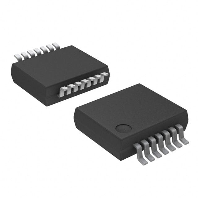
- Package: SOIC (Small Outline Integrated Circuit)
- Essence: Serial-in, parallel-out shift register
- Packaging/Quantity: Tape and reel, 2500 pieces per reel
Specifications
- Logic Family: HCT
- Number of Bits: 8
- Input Voltage: 2V to 6V
- Output Voltage: 0V to VCC
- Operating Temperature Range: -40°C to +125°C
- Maximum Clock Frequency: 25 MHz
- Propagation Delay: 13 ns (typical)
Detailed Pin Configuration
The 74HCT164DB,112 has a total of 14 pins. The pin configuration is as follows:
- GND (Ground)
- SER (Serial Data Input)
- QA (Parallel Output A)
- QB (Parallel Output B)
- QC (Parallel Output C)
- QD (Parallel Output D)
- QE (Parallel Output E)
- QF (Parallel Output F)
- QG (Parallel Output G)
- QH (Parallel Output H)
- MR (Master Reset)
- CP (Clock Pulse Input)
- VCC (Positive Power Supply)
- GND (Ground)
Functional Features
- Serial-in, parallel-out shifting of data
- Asynchronous master reset for clearing the register
- Positive-edge triggered clock input
- Outputs can be used as inputs for cascading multiple devices
- High-speed operation allows for efficient data transfer
- Low power consumption makes it suitable for battery-powered applications
Advantages and Disadvantages
Advantages: - High-speed operation enables quick data processing - Low power consumption prolongs battery life - Compact SOIC package saves board space - Versatile for various applications due to cascading capability
Disadvantages: - Limited number of bits (8) may not be sufficient for certain applications - Requires an external clock signal for operation
Working Principles
The 74HCT164DB,112 is a serial-in, parallel-out shift register. It receives data serially through the SER pin and shifts it into the register on each rising edge of the clock pulse applied to the CP pin. The shifted data is then available in parallel form at the QA to QH output pins. The MR pin allows for asynchronous clearing of the register, resetting all outputs to a low state.
Detailed Application Field Plans
The 74HCT164DB,112 can be used in various applications that require serial-to-parallel data conversion. Some potential application fields include:
- LED Display Control: The shift register can be used to control multiple LEDs, allowing for dynamic patterns and animations.
- Data Storage: It can be utilized as part of a memory system for temporary storage of data during processing.
- Serial Communication: The device can be employed in serial communication protocols to convert incoming serial data into parallel format for further processing.
Detailed and Complete Alternative Models
Some alternative models to the 74HCT164DB,112 are:
- SN74HC164N: Similar 8-bit shift register with parallel outputs, offered in DIP (Dual Inline Package).
- CD4015BE: Dual 4-bit static shift register with parallel outputs, available in DIP package.
- 74LS164: 8-bit shift register with parallel outputs, compatible with TTL logic levels.
These alternative models offer similar functionality and can be considered based on specific requirements and availability.
Word count: 445 words
Enumere 10 preguntas y respuestas comunes relacionadas con la aplicación de 74HCT164DB,112 en soluciones técnicas
Sure! Here are 10 common questions and answers related to the application of 74HCT164DB,112 in technical solutions:
Q: What is the function of the 74HCT164DB,112? A: The 74HCT164DB,112 is an 8-bit serial-in/parallel-out shift register that can be used for data storage and transfer in digital circuits.
Q: What is the operating voltage range of the 74HCT164DB,112? A: The 74HCT164DB,112 operates within a voltage range of 2V to 6V.
Q: How many inputs does the 74HCT164DB,112 have? A: The 74HCT164DB,112 has a single serial input and eight parallel inputs.
Q: Can the 74HCT164DB,112 be cascaded to increase the number of outputs? A: Yes, multiple 74HCT164DB,112 chips can be cascaded together to increase the number of outputs.
Q: What is the maximum clock frequency supported by the 74HCT164DB,112? A: The 74HCT164DB,112 can operate at a maximum clock frequency of 25 MHz.
Q: Does the 74HCT164DB,112 have any built-in output latches? A: No, the 74HCT164DB,112 does not have built-in output latches. The outputs directly reflect the state of the internal shift register.
Q: Can the 74HCT164DB,112 be used for both serial-to-parallel and parallel-to-serial conversion? A: Yes, the 74HCT164DB,112 can be used for both serial-to-parallel and parallel-to-serial conversion depending on the configuration.
Q: What is the power consumption of the 74HCT164DB,112? A: The power consumption of the 74HCT164DB,112 depends on the operating voltage and the activity of the inputs and outputs.
Q: Can the 74HCT164DB,112 be used in high-speed applications? A: Yes, the 74HCT164DB,112 is designed to operate at high clock frequencies, making it suitable for high-speed applications.
Q: Are there any specific application examples for the 74HCT164DB,112? A: The 74HCT164DB,112 can be used in various applications such as LED matrix displays, shift register-based data storage, and serial communication interfaces.
Please note that the answers provided here are general and may vary based on specific datasheet information and application requirements.