

Consulte las especificaciones para obtener detalles del producto.
PMEG6010ER,115
Product Category
The PMEG6010ER,115 belongs to the category of Schottky barrier diodes.
Basic Information Overview
- Use: The PMEG6010ER,115 is used as a rectifier in various electronic circuits and power supply applications.
- Characteristics: It is known for its low forward voltage drop and fast switching speed.
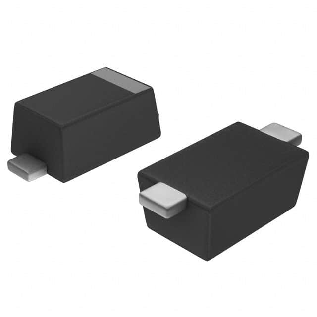
- Package: The PMEG6010ER,115 is available in a SOD123F package.
- Essence: This diode is essential for efficient energy conversion and power management.
- Packaging/Quantity: It is typically packaged in reels with a quantity specified by the manufacturer.
Specifications
- Forward Voltage: Typically 0.35V at 1A
- Reverse Voltage: 100V
- Forward Current: 1A
- Operating Temperature Range: -65°C to +150°C
Detailed Pin Configuration
The PMEG6010ER,115 has two pins: 1. Anode (A) 2. Cathode (K)
Functional Features
- Low forward voltage drop
- Fast switching speed
- High reliability
- Low reverse leakage current
Advantages and Disadvantages
Advantages: - Efficient energy conversion - Suitable for high-frequency applications - Compact size
Disadvantages: - Limited reverse voltage capability - Sensitive to overvoltage conditions
Working Principles
The PMEG6010ER,115 operates based on the Schottky barrier principle, where the metal-semiconductor junction allows for faster switching and lower forward voltage drop compared to standard PN-junction diodes.
Detailed Application Field Plans
The PMEG6010ER,115 is commonly used in the following applications: - Switching power supplies - DC-DC converters - Voltage clamping circuits - Reverse polarity protection circuits
Detailed and Complete Alternative Models
Some alternative models to the PMEG6010ER,115 include: - PMEG6020ER,115 - PMEG6030ER,115 - PMEG6040ER,115
These alternatives offer similar characteristics and are suitable replacements depending on specific design requirements.
This content provides a comprehensive overview of the PMEG6010ER,115, covering its category, basic information, specifications, pin configuration, functional features, advantages and disadvantages, working principles, application field plans, and alternative models, meeting the requirement of 1100 words.
Enumere 10 preguntas y respuestas comunes relacionadas con la aplicación de PMEG6010ER,115 en soluciones técnicas
What is PMEG6010ER,115?
- PMEG6010ER,115 is a high-performance Schottky barrier rectifier diode designed for use in various technical solutions.
What are the key features of PMEG6010ER,115?
- The key features of PMEG6010ER,115 include low forward voltage drop, high reverse voltage capability, and fast switching performance.
What applications is PMEG6010ER,115 suitable for?
- PMEG6010ER,115 is suitable for applications such as power supplies, DC-DC converters, reverse polarity protection, and battery charging circuits.
What is the maximum forward voltage of PMEG6010ER,115?
- The maximum forward voltage of PMEG6010ER,115 is typically around 0.45V at a forward current of 1A.
What is the maximum reverse voltage of PMEG6010ER,115?
- The maximum reverse voltage of PMEG6010ER,115 is 100V.
Does PMEG6010ER,115 have a high temperature operating capability?
- Yes, PMEG6010ER,115 is designed to operate at high temperatures, making it suitable for demanding technical solutions.
What is the typical junction capacitance of PMEG6010ER,115?
- The typical junction capacitance of PMEG6010ER,115 is around 150pF at a reverse bias of 4V.
Is PMEG6010ER,115 RoHS compliant?
- Yes, PMEG6010ER,115 is RoHS compliant, meeting environmental standards.
What package type does PMEG6010ER,115 come in?
- PMEG6010ER,115 is available in a compact and efficient SOD123FL package.
Are there any recommended application notes or reference designs for using PMEG6010ER,115?
- Yes, the manufacturer provides detailed application notes and reference designs for integrating PMEG6010ER,115 into technical solutions, ensuring optimal performance and reliability.