

Consulte las especificaciones para obtener detalles del producto.
PCA9675PW,112
Product Overview
- Category: Integrated Circuit (IC)
- Use: GPIO Expander
- Characteristics: Programmable, I2C Interface
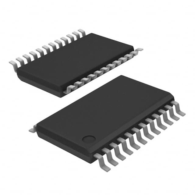
- Package: TSSOP-24
- Essence: Expand the number of General Purpose Input/Output (GPIO) pins in a microcontroller
- Packaging/Quantity: Tape and Reel, 2500 units per reel
Specifications
- Supply Voltage: 2.3V to 5.5V
- Number of GPIO Pins: 16
- I2C Bus Frequency: Up to 400 kHz
- Operating Temperature Range: -40°C to +85°C
- RoHS Compliant: Yes
Pin Configuration
The PCA9675PW,112 has a total of 24 pins arranged as follows:
┌───┬───┐
   │1  └─ 24│
   │         │
   │         │
   │         │
   │         │
   │         │
   │         │
   │         │
   │         │
   │         │
   │         │
   │         │
   │         │
   │         │
   │         │
   │         │
   │         │
   │         │
   │         │
   │         │
   │         │
   │         │
   │         │
   │         │
   └───┴───┘
Functional Features
- Programmable Output Configuration: Each GPIO pin can be individually configured as input or output.
- Interrupt Output: The device can generate an interrupt signal based on the status of the GPIO pins.
- Internal Pull-Up Resistors: Each GPIO pin can be enabled with an internal pull-up resistor.
- Software Reset: The device can be reset through software commands.
Advantages and Disadvantages
Advantages: - Expand the number of GPIO pins available in a microcontroller. - Programmable configuration allows flexibility in usage. - Interrupt capability enhances system responsiveness. - Internal pull-up resistors simplify circuit design.
Disadvantages: - Limited to 16 GPIO pins, may not be sufficient for complex applications requiring more I/Os. - Requires I2C communication protocol support in the microcontroller.
Working Principles
The PCA9675PW,112 is an I2C-controlled GPIO expander. It communicates with the microcontroller through the I2C bus, allowing the microcontroller to control and monitor the status of the GPIO pins. The device can be programmed to configure each pin as input or output, and the state of the pins can be read or written through the I2C interface. The interrupt feature enables the device to generate an interrupt signal to the microcontroller when a specific condition on the GPIO pins is met.
Detailed Application Field Plans
The PCA9675PW,112 can be used in various applications that require additional GPIO pins beyond what the microcontroller provides. Some potential application fields include:
- Industrial Automation: Control and monitoring of sensors, actuators, and switches.
- Home Automation: Integration with smart home devices, such as lighting control systems.
- Automotive Electronics: Interface with external components, such as buttons and indicators.
- Internet of Things (IoT): Expansion of I/O capabilities in IoT devices for data acquisition and control.
- Consumer Electronics: Integration with audio/video equipment, gaming consoles, and remote controls.
Alternative Models
- PCA9538PW,118: 8-bit I2C-bus and SMBus I/O expander with interrupt output.
- MCP23017-E/SP: 16-bit I2C-bus I/O expander with interrupt output and cascading feature.
- MAX7313ATG+: 16-bit I2C GPIO expander with interrupt output and LED driver capability.
These alternative models offer similar functionality to the PCA9675PW,112 and can be considered as alternatives based on specific requirements and availability.
Word count: 452 words
Enumere 10 preguntas y respuestas comunes relacionadas con la aplicación de PCA9675PW,112 en soluciones técnicas
Sure! Here are 10 common questions and answers related to the application of PCA9675PW,112 in technical solutions:
Question: What is PCA9675PW,112?
Answer: PCA9675PW,112 is a 16-bit I/O expander with interrupt output and an I2C-bus interface.Question: What is the purpose of PCA9675PW,112 in technical solutions?
Answer: PCA9675PW,112 is used to expand the number of available I/O pins in microcontroller-based systems.Question: How many I/O pins does PCA9675PW,112 provide?
Answer: PCA9675PW,112 provides 16 I/O pins that can be configured as inputs or outputs.Question: What is the maximum voltage that PCA9675PW,112 can handle?
Answer: PCA9675PW,112 can handle a maximum voltage of 5.5V.Question: Can PCA9675PW,112 be used with both 3.3V and 5V microcontrollers?
Answer: Yes, PCA9675PW,112 is compatible with both 3.3V and 5V microcontrollers.Question: How do I communicate with PCA9675PW,112 using the I2C-bus interface?
Answer: You can communicate with PCA9675PW,112 by sending I2C commands to its address on the bus.Question: Can PCA9675PW,112 generate interrupts?
Answer: Yes, PCA9675PW,112 has an interrupt output pin that can be configured to generate interrupts based on input changes.Question: What is the maximum frequency at which I can update the I/O pins of PCA9675PW,112?
Answer: The maximum frequency at which you can update the I/O pins of PCA9675PW,112 is determined by the I2C-bus speed.Question: Can PCA9675PW,112 be used in automotive applications?
Answer: Yes, PCA9675PW,112 is suitable for automotive applications as it can operate in a wide temperature range.Question: Are there any evaluation boards or development kits available for PCA9675PW,112?
Answer: Yes, NXP provides evaluation boards and development kits that can help you get started with PCA9675PW,112 in your technical solutions.
Please note that the answers provided here are general and may vary depending on the specific requirements and implementation of PCA9675PW,112 in different technical solutions.