

Consulte las especificaciones para obtener detalles del producto.
Encyclopedia Entry: 74ACTQ74PC
Product Information Overview
- Category: Integrated Circuit (IC)
- Use: Digital Logic Flip-Flop
- Characteristics: High-speed, low-power consumption
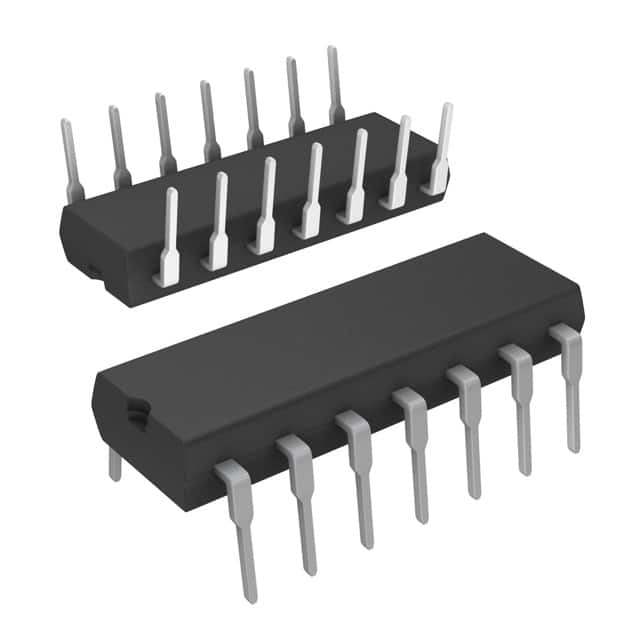
- Package: Plastic DIP (Dual In-line Package)
- Essence: Dual Positive-Edge-Triggered D-Type Flip-Flop
- Packaging/Quantity: Tube packaging, typically containing 25 pieces
Specifications
The 74ACTQ74PC is a dual positive-edge-triggered D-type flip-flop integrated circuit. It operates on a supply voltage range of 4.5V to 5.5V and offers high-speed performance combined with low power consumption. The IC is designed to work in various digital logic applications where reliable data storage and transfer are required.
Detailed Pin Configuration
The 74ACTQ74PC has a total of 14 pins, which are assigned specific functions as follows:
- Pin 1: Data Input (D1)
- Pin 2: Clock Input (CLK1)
- Pin 3: Set Input (SET1)
- Pin 4: Reset Input (RESET1)
- Pin 5: Output (Q1)
- Pin 6: Complementary Output (Q̅1)
- Pin 7: Ground (GND)
- Pin 8: Output (Q̅1)
- Pin 9: Complementary Output (Q1)
- Pin 10: Reset Input (RESET2)
- Pin 11: Set Input (SET2)
- Pin 12: Clock Input (CLK2)
- Pin 13: Data Input (D2)
- Pin 14: Supply Voltage (VCC)
Functional Features
The 74ACTQ74PC offers the following functional features:
- Dual flip-flop design allows for independent operation of two separate data inputs and clock inputs.
- Positive-edge-triggered functionality ensures reliable data storage and transfer on the rising edge of the clock signal.
- Set and reset inputs provide control over the output state, allowing for synchronous or asynchronous operation.
- Complementary outputs provide both inverted and non-inverted versions of the stored data.
Advantages and Disadvantages
Advantages of the 74ACTQ74PC include:
- High-speed performance enables efficient data processing in time-critical applications.
- Low power consumption contributes to energy-efficient designs.
- Dual flip-flop configuration offers flexibility in circuit design.
Disadvantages of the 74ACTQ74PC include:
- Limited voltage supply range restricts its usability in certain applications.
- Plastic DIP package may not be suitable for environments with high temperatures or mechanical stress.
Working Principles
The 74ACTQ74PC operates based on positive-edge-triggered D-type flip-flop principles. When a rising edge is detected on the clock input, the data input is sampled and stored in the flip-flop. The stored data is then available at the output pins until the next clock cycle. The set and reset inputs allow for controlling the output state, either synchronously or asynchronously.
Detailed Application Field Plans
The 74ACTQ74PC can be utilized in various digital logic applications, including but not limited to:
- Data storage and transfer in microprocessors and microcontrollers.
- State machine implementations.
- Clock synchronization circuits.
- Register and counter designs.
- Communication systems requiring reliable data transmission.
Detailed and Complete Alternative Models
Alternative models that offer similar functionality to the 74ACTQ74PC include:
- 74HC74: High-speed CMOS dual D-type flip-flop.
- CD4013: Dual D-type flip-flop with complementary outputs.
- SN74LS74: Dual positive-edge-triggered D-type flip-flop with preset and clear inputs.
These alternative models can be considered based on specific project requirements, availability, and cost considerations.
In conclusion, the 74ACTQ74PC is a high-speed, low-power dual positive-edge-triggered D-type flip-flop IC. Its versatile functionality and reliable performance make it suitable for various digital logic applications.
Enumere 10 preguntas y respuestas comunes relacionadas con la aplicación de 74ACTQ74PC en soluciones técnicas
Sure! Here are 10 common questions and answers related to the application of 74ACTQ74PC in technical solutions:
Question: What is the 74ACTQ74PC?
- Answer: The 74ACTQ74PC is a dual D-type flip-flop integrated circuit (IC) that operates on a supply voltage range of 2.0V to 5.5V.Question: What is the purpose of using the 74ACTQ74PC?
- Answer: The 74ACTQ74PC is commonly used for storing and transferring binary data in digital circuits, making it useful for various applications such as counters, registers, and memory units.Question: What is the maximum clock frequency supported by the 74ACTQ74PC?
- Answer: The 74ACTQ74PC can operate at a maximum clock frequency of 250 MHz.Question: How many flip-flops are present in the 74ACTQ74PC?
- Answer: The 74ACTQ74PC contains two independent D-type flip-flops.Question: What is the input voltage range for logic high and logic low levels?
- Answer: For logic high, the input voltage range is typically between 2.0V and VCC (supply voltage). For logic low, it is typically between GND (ground) and 0.8V.Question: Can the 74ACTQ74PC be cascaded to create larger storage units?
- Answer: Yes, multiple 74ACTQ74PC ICs can be cascaded together to create larger storage units or longer shift registers.Question: Does the 74ACTQ74PC have any built-in protection features?
- Answer: Yes, the 74ACTQ74PC has built-in protection against electrostatic discharge (ESD) and excessive power dissipation.Question: What is the typical propagation delay of the 74ACTQ74PC?
- Answer: The typical propagation delay for the 74ACTQ74PC is around 4.5 ns.Question: Can the 74ACTQ74PC be used in both synchronous and asynchronous applications?
- Answer: Yes, the 74ACTQ74PC can be used in both synchronous and asynchronous applications, depending on the specific requirements of the circuit.Question: Are there any special considerations for power supply decoupling when using the 74ACTQ74PC?
- Answer: Yes, it is recommended to use bypass capacitors near the power supply pins of the IC to ensure stable operation and minimize noise interference.
Please note that the answers provided here are general and may vary depending on the specific datasheet and application guidelines provided by the manufacturer.