

Consulte las especificaciones para obtener detalles del producto.
Encyclopedia Entry: 74F191SJ
Product Overview
Category
The 74F191SJ belongs to the category of integrated circuits (ICs) and specifically falls under the family of synchronous counters.
Use
This IC is primarily used for counting and storing binary data in electronic circuits. It can be employed in various applications that require sequential counting or frequency division.
Characteristics
- Synchronous operation: The 74F191SJ operates synchronously with an external clock signal, ensuring accurate counting.
- High-speed performance: This IC is designed to operate at high clock frequencies, making it suitable for time-critical applications.
- Low power consumption: It features low power dissipation, making it energy-efficient.
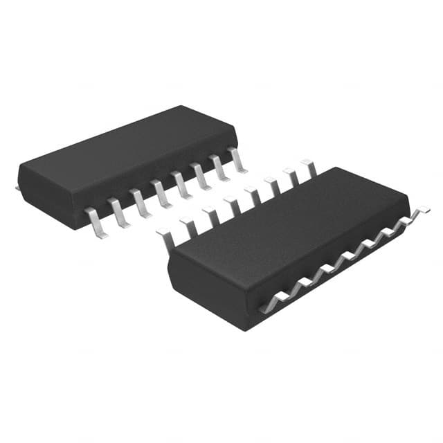
- Compact package: The 74F191SJ is available in a small outline package (SOP), enabling space-saving integration into electronic systems.
- Versatile input/output options: It offers multiple input and output pins for flexible connectivity.
Package and Quantity
The 74F191SJ is typically packaged in a 16-pin small outline package (SOP). It is commonly available in reels or tubes containing a quantity of 250 units per package.
Specifications
- Supply voltage: 4.5V to 5.5V
- Operating temperature range: -40°C to +85°C
- Maximum clock frequency: 50 MHz
- Counting range: 0 to 15 (4-bit binary)
- Input/output voltage levels: TTL-compatible
Pin Configuration
The pin configuration of the 74F191SJ is as follows:
+---+--+---+
   QD |1     16| VCC
   QC |2     15| MR
   QB |3     14| CP
   QA |4     13| CE
  GND |5     12| PE
   LD |6     11| TC
   PL |7     10| RC
   PI |8      9| CO
       +--------+
Functional Features
- Synchronous counting: The IC counts sequentially based on the clock input signal.
- Parallel load capability: It allows loading of a specific count value in parallel, bypassing the sequential counting process.
- Asynchronous reset: The MR (Master Reset) pin resets the counter to its initial state asynchronously.
- Carry output: The CO (Carry Out) pin provides a carry signal when the counter reaches its maximum count value.
- Terminal count output: The TC (Terminal Count) pin indicates when the counter has reached its maximum count value.
Advantages and Disadvantages
Advantages
- High-speed operation enables efficient counting in time-critical applications.
- Low power consumption contributes to energy efficiency.
- Compact package facilitates integration into space-constrained electronic systems.
- Versatile input/output options allow for flexible connectivity.
Disadvantages
- Limited counting range (0 to 15) restricts its use in applications requiring larger count values.
- Requires an external clock signal for synchronous operation.
Working Principles
The 74F191SJ operates as a synchronous binary counter. It counts sequentially based on the rising edge of the clock input signal. The counter can be loaded with a specific count value in parallel or incremented by one with each clock pulse. When the counter reaches its maximum count value, it generates a carry signal and sets the terminal count output.
Application Field Plans
The 74F191SJ finds application in various fields, including: 1. Digital frequency dividers 2. Industrial automation systems 3. Electronic test equipment 4. Communication devices 5. Automotive electronics
Alternative Models
Some alternative models that provide similar functionality to the 74F191SJ include: - 74HC191: A CMOS version of the synchronous counter with a wider operating voltage range. - 74LS191: A low-power Schottky TTL version of the synchronous counter.
These alternative models can be considered based on specific application requirements and compatibility with existing circuitry.
Word count: 520 words
Enumere 10 preguntas y respuestas comunes relacionadas con la aplicación de 74F191SJ en soluciones técnicas
Sure! Here are 10 common questions and answers related to the application of 74F191SJ in technical solutions:
Q: What is the 74F191SJ? A: The 74F191SJ is a synchronous up/down binary counter with a preset feature.
Q: What is the maximum clock frequency supported by the 74F191SJ? A: The 74F191SJ can operate at a maximum clock frequency of 100 MHz.
Q: How many bits does the 74F191SJ have? A: The 74F191SJ is a 4-bit counter, meaning it can count from 0 to 15 (binary).
Q: Can the 74F191SJ count both up and down? A: Yes, the 74F191SJ has separate up and down counting modes.
Q: How do I set the initial value for the counter? A: The 74F191SJ has a preset feature that allows you to set the initial value using the parallel load inputs.
Q: What is the purpose of the carry/borrow output pin? A: The carry/borrow output pin indicates when the counter reaches its maximum or minimum value during counting.
Q: Can I cascade multiple 74F191SJ counters together? A: Yes, you can cascade multiple 74F191SJ counters to create larger counters with more bits.
Q: What is the power supply voltage range for the 74F191SJ? A: The 74F191SJ operates with a power supply voltage range of 4.5V to 5.5V.
Q: Does the 74F191SJ have any asynchronous inputs? A: No, the 74F191SJ is a synchronous counter and does not have any asynchronous inputs.
Q: Can I use the 74F191SJ in high-speed applications? A: Yes, the 74F191SJ is designed for high-speed operation and can be used in various high-frequency applications.
Please note that these answers are general and may vary depending on the specific implementation and datasheet of the 74F191SJ.