

Consulte las especificaciones para obtener detalles del producto.
74HC138DTR2G
Product Overview
- Category: Integrated Circuit (IC)
- Use: Decoder/Demultiplexer
- Characteristics: High-speed, low-power consumption
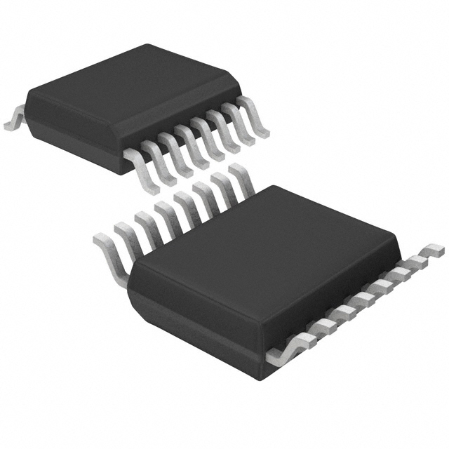
- Package: SOIC-16
- Essence: Decodes binary input signals into multiple output lines
- Packaging/Quantity: Tape and Reel, 2500 units per reel
Specifications
- Supply Voltage Range: 2V to 6V
- Input Voltage Range: 0V to VCC
- Output Voltage Range: 0V to VCC
- Maximum Operating Frequency: 33 MHz
- Number of Inputs: 3
- Number of Outputs: 8
Detailed Pin Configuration
- GND - Ground
- A0 - Binary Input 0
- A1 - Binary Input 1
- A2 - Binary Input 2
- E1 - Enable Input 1
- E2 - Enable Input 2
- E3 - Enable Input 3
- Y0 - Output 0
- Y1 - Output 1
- Y2 - Output 2
- Y3 - Output 3
- Y4 - Output 4
- Y5 - Output 5
- Y6 - Output 6
- Y7 - Output 7
- VCC - Power Supply
Functional Features
The 74HC138DTR2G is a decoder/demultiplexer IC that takes three binary inputs (A0, A1, A2) and decodes them into eight mutually exclusive outputs (Y0-Y7). The enable inputs (E1, E2, E3) control the operation of the decoder. When the enable inputs are active, the selected output line becomes low, while all other output lines remain high. This IC operates at high speed and consumes low power, making it suitable for various applications.
Advantages and Disadvantages
Advantages: - High-speed operation - Low power consumption - Compact package size - Easy to use and integrate into circuits
Disadvantages: - Limited number of inputs and outputs - Not suitable for complex decoding tasks
Working Principles
The 74HC138DTR2G works based on the principle of binary decoding. The three input lines (A0, A1, A2) represent a binary code, and the decoder interprets this code to activate one of the eight output lines (Y0-Y7). The enable inputs (E1, E2, E3) control the operation of the decoder. When an enable input is active, the corresponding output line becomes low, while all other output lines remain high.
Detailed Application Field Plans
The 74HC138DTR2G finds applications in various fields, including:
- Address Decoding: Used in microcontrollers and memory systems to decode address signals and select specific memory locations.
- Data Multiplexing: Enables the selection of different data sources based on binary input codes.
- LED Matrix Control: Controls the activation of individual LEDs in a matrix display based on binary input signals.
- Digital Signal Processing: Used in signal processing circuits to select specific processing paths based on input codes.
Detailed and Complete Alternative Models
Some alternative models to the 74HC138DTR2G include:
- 74LS138: Similar functionality but operates at a lower speed and higher power consumption.
- CD74HC138: Equivalent functionality with minor differences in electrical characteristics.
- SN74HC138: Similar functionality with variations in package type and pin configuration.
These alternative models can be considered based on specific requirements and availability.
Word count: 388
Enumere 10 preguntas y respuestas comunes relacionadas con la aplicación de 74HC138DTR2G en soluciones técnicas
Sure! Here are 10 common questions and answers related to the application of 74HC138DTR2G in technical solutions:
Q: What is the 74HC138DTR2G? A: The 74HC138DTR2G is a 3-to-8 line decoder/demultiplexer integrated circuit (IC) that can be used to decode binary information and select one of eight outputs based on the input signals.
Q: What is the voltage supply range for the 74HC138DTR2G? A: The 74HC138DTR2G operates with a voltage supply range of 2V to 6V.
Q: How many inputs does the 74HC138DTR2G have? A: The 74HC138DTR2G has three inputs, namely A0, A1, and A2, which are used to select one of the eight outputs.
Q: What is the maximum output current of the 74HC138DTR2G? A: The maximum output current of the 74HC138DTR2G is 25mA per output pin.
Q: Can the 74HC138DTR2G be used as a demultiplexer? A: Yes, the 74HC138DTR2G can be used as a demultiplexer by connecting the appropriate input signals and using the selected output to route the input signal to the desired destination.
Q: How can I cascade multiple 74HC138DTR2G ICs? A: To cascade multiple 74HC138DTR2G ICs, connect the outputs of one IC to the inputs of the next IC, while ensuring that the enable (E1, E2, E3) pins are connected in parallel.
Q: What is the purpose of the enable (E1, E2, E3) pins on the 74HC138DTR2G? A: The enable pins on the 74HC138DTR2G are used to enable or disable the decoder/demultiplexer. When one or more enable pins are low (logic 0), the outputs are disabled.
Q: Can the 74HC138DTR2G be used with both TTL and CMOS logic levels? A: Yes, the 74HC138DTR2G is compatible with both TTL and CMOS logic levels, making it versatile for use in various digital systems.
Q: What is the typical propagation delay of the 74HC138DTR2G? A: The typical propagation delay of the 74HC138DTR2G is around 13 ns.
Q: What are some common applications of the 74HC138DTR2G? A: The 74HC138DTR2G is commonly used in address decoding, memory selection, data routing, and general-purpose digital logic applications.
Please note that these answers are general and may vary depending on specific datasheet specifications and application requirements.