

Consulte las especificaciones para obtener detalles del producto.
MC14024BD
Product Overview
- Category: Integrated Circuit
- Use: Logic Gate
- Characteristics: High-speed, low-power consumption
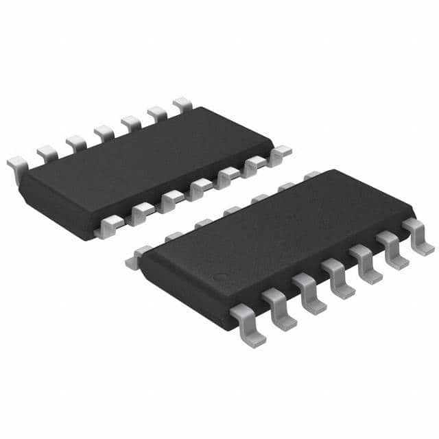
- Package: DIP (Dual In-line Package)
- Essence: Binary Counter
- Packaging/Quantity: Tube packaging, 25 pieces per tube
Specifications
- Supply Voltage: 3V to 18V
- Logic Family: CMOS
- Number of Stages: 7
- Operating Temperature Range: -55°C to +125°C
- Propagation Delay: 60 ns (typical)
Detailed Pin Configuration
The MC14024BD has a total of 14 pins. The pin configuration is as follows:
- Pin 1: Clock Input (CP1)
- Pin 2: Clock Input (CP0)
- Pin 3: Reset Input (MR)
- Pin 4: Output (Q0)
- Pin 5: Output (Q1)
- Pin 6: Output (Q2)
- Pin 7: Output (Q3)
- Pin 8: Output (Q4)
- Pin 9: Output (Q5)
- Pin 10: Output (Q6)
- Pin 11: Ground (GND)
- Pin 12: Output Enable (OE)
- Pin 13: Carry Output (CO)
- Pin 14: Supply Voltage (VDD)
Functional Features
The MC14024BD is a binary counter that can count up to 127 in binary form. It operates on a clock input and provides outputs for each stage of the counter. The counter can be reset using the reset input. The output enable pin allows the user to disable the outputs when not needed. The carry output pin provides a carry signal when the counter reaches its maximum value.
Advantages and Disadvantages
Advantages: - High-speed operation - Low-power consumption - Wide operating voltage range - Compact DIP package for easy integration
Disadvantages: - Limited counting range (up to 127) - Not suitable for applications requiring higher counting capabilities
Working Principles
The MC14024BD is based on CMOS technology, which allows for high-speed operation and low power consumption. The binary counter works by incrementing its internal count value on each clock pulse. When the counter reaches its maximum value, it generates a carry signal. The reset input can be used to set the counter back to zero. The output enable pin allows the user to control the output state of the counter.
Detailed Application Field Plans
The MC14024BD is commonly used in various digital systems and applications, including:
- Frequency Dividers: The binary counter can be used as a frequency divider to generate lower frequency signals from a higher frequency source.
- Time Delay Circuits: By utilizing the counter's clock input and outputs, time delay circuits can be implemented for precise timing requirements.
- Event Counters: The MC14024BD can be used to count events or pulses in applications such as industrial automation or electronic instrumentation.
- Sequence Generators: With the ability to count in binary form, the counter can be used to generate specific sequences of numbers for various applications.
Detailed and Complete Alternative Models
Some alternative models that offer similar functionality to the MC14024BD are:
- CD4024BE: This is a 7-stage binary counter with similar specifications and pin configuration.
- SN74HC4040N: A 12-stage binary counter with additional features like asynchronous reset and higher counting range.
- CD40193BE: A 4-bit synchronous up/down binary counter with similar characteristics.
These alternative models can be considered based on specific application requirements and desired features.
Word count: 430 words
Enumere 10 preguntas y respuestas comunes relacionadas con la aplicación de MC14024BD en soluciones técnicas
Sure! Here are 10 common questions and answers related to the application of MC14024BD in technical solutions:
Q: What is MC14024BD? A: MC14024BD is a specific type of integrated circuit (IC) that consists of 7 logic gates, specifically NOR gates.
Q: What are the typical applications of MC14024BD? A: MC14024BD can be used in various digital logic applications such as signal inversion, logic gate implementation, and waveform generation.
Q: What is the operating voltage range for MC14024BD? A: The operating voltage range for MC14024BD is typically between 3V and 18V.
Q: Can MC14024BD be used in low-power applications? A: Yes, MC14024BD is designed to operate at relatively low power levels, making it suitable for low-power applications.
Q: How many NOR gates are there in MC14024BD? A: MC14024BD contains a total of 7 NOR gates.
Q: What is the maximum output current capability of MC14024BD? A: The maximum output current capability of MC14024BD is typically around 8 mA.
Q: Is MC14024BD compatible with TTL logic levels? A: Yes, MC14024BD is compatible with TTL (Transistor-Transistor Logic) logic levels, which makes it versatile for interfacing with other TTL devices.
Q: Can MC14024BD be used in high-frequency applications? A: MC14024BD is not specifically designed for high-frequency applications, but it can still function at moderate frequencies depending on the specific requirements.
Q: Does MC14024BD have built-in protection features? A: MC14024BD does not have built-in protection features, so external measures may be required to protect the IC from voltage spikes or electrostatic discharge.
Q: Are there any specific layout considerations for using MC14024BD? A: It is generally recommended to follow good PCB layout practices, such as minimizing trace lengths and providing proper decoupling capacitors, to ensure optimal performance when using MC14024BD.
Please note that these answers are general and may vary depending on the specific application and requirements.