

Consulte las especificaciones para obtener detalles del producto.
MC74HC595ADTG
Product Overview
- Category: Integrated Circuit
- Use: Shift Register
- Characteristics: High-Speed, Serial-In Parallel-Out
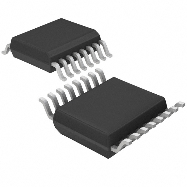
- Package: SOIC (Small Outline Integrated Circuit)
- Essence: 8-Bit Serial-In, Parallel-Out Shift Register with Output Latches
- Packaging/Quantity: Tape and Reel, 2500 pieces per reel
Specifications
- Supply Voltage: 2V to 6V
- Operating Temperature Range: -40°C to +85°C
- Input Voltage: 0V to VCC
- Output Voltage: 0V to VCC
- Maximum Clock Frequency: 25 MHz
- Number of Stages: 8
- Latch-Up Performance: Exceeds 300 mA per JESD 17
Pin Configuration
The MC74HC595ADTG has a total of 16 pins. The pin configuration is as follows:
- QH' (Output)
- QH (Output)
- DS (Serial Data Input)
- OE (Output Enable)
- ST_CP (Storage Register Clock Input)
- SH_CP (Shift Register Clock Input)
- MR (Master Reset)
- GND (Ground)
- QG (Output)
- QF (Output)
- QE (Output)
- QD (Output)
- QC (Output)
- QB (Output)
- QA (Output)
- VCC (Supply Voltage)
Functional Features
- Serial-in, parallel-out shift register with output latches
- High-speed operation with a maximum clock frequency of 25 MHz
- Wide operating voltage range from 2V to 6V
- Output enable control for easy cascading of multiple devices
- Master reset for clearing the shift register and output latches
Advantages and Disadvantages
Advantages: - High-speed operation allows for quick data transfer - Output enable control simplifies cascading of multiple devices - Wide operating voltage range provides flexibility in different applications
Disadvantages: - Limited number of stages (8) may not be sufficient for certain complex applications - Lack of built-in protection features against ESD or overvoltage events
Working Principles
The MC74HC595ADTG is a shift register that allows serial data to be converted into parallel data. It consists of an 8-bit shift register and output latches. The serial data is input through the DS pin and shifted through the register with each clock pulse applied to the SHCP pin. The STCP pin is used to latch the parallel data into the output registers. The output enable (OE) pin controls the output state of the device.
Detailed Application Field Plans
The MC74HC595ADTG can be used in various applications, including:
- LED Matrix Displays: The shift register can be used to control multiple LEDs in a matrix display, allowing for efficient use of microcontroller pins.
- Serial-to-Parallel Conversion: It can be used to convert serial data from sensors or communication modules into parallel data for further processing.
- Data Storage and Transfer: The output latches allow for temporary storage of data before it is transferred to other devices or systems.
Alternative Models
Here are some alternative models that provide similar functionality:
- SN74HC595N: This is a DIP (Dual In-line Package) version of the shift register.
- CD4094BE: This is another 8-bit serial-in, parallel-out shift register with output latches.
- 74HCT595: This model offers compatibility with both CMOS and TTL logic levels.
These alternative models can be considered based on specific requirements and availability.
In conclusion, the MC74HC595ADTG is a high-speed shift register with output latches, suitable for various applications such as LED matrix displays, serial-to-parallel conversion, and data storage. It offers advantages in terms of speed, voltage range, and cascading capability. However, it has limitations in terms of the number of stages and lack of built-in protection features. Alternative models provide options for different package types and compatibility with different logic levels.
Enumere 10 preguntas y respuestas comunes relacionadas con la aplicación de MC74HC595ADTG en soluciones técnicas
Sure! Here are 10 common questions and answers related to the application of MC74HC595ADTG:
Q: What is MC74HC595ADTG? A: MC74HC595ADTG is a shift register IC (integrated circuit) that can be used to expand the number of digital outputs in a microcontroller-based system.
Q: How does MC74HC595ADTG work? A: It works by shifting data into its internal registers and then outputting the data sequentially on its output pins.
Q: What is the maximum number of outputs that can be controlled using MC74HC595ADTG? A: MC74HC595ADTG has 8 output pins, so it can control up to 8 digital outputs.
Q: Can MC74HC595ADTG be used to control LEDs? A: Yes, it is commonly used to control LEDs as it allows for controlling multiple LEDs using fewer microcontroller pins.
Q: How do I connect MC74HC595ADTG to a microcontroller? A: You need to connect the serial data input (DS), clock input (SHCP), and latch input (STCP) pins of MC74HC595ADTG to the corresponding pins of the microcontroller.
Q: Can MC74HC595ADTG be daisy-chained to control more than 8 outputs? A: Yes, multiple MC74HC595ADTG ICs can be daisy-chained together to control more than 8 outputs.
Q: What is the advantage of using MC74HC595ADTG over directly connecting LEDs to a microcontroller? A: Using MC74HC595ADTG reduces the number of microcontroller pins required to control multiple LEDs, thus saving valuable resources.
Q: Can MC74HC595ADTG be used with other types of digital components besides LEDs? A: Yes, it can be used to control various digital components such as relays, transistors, and even other shift registers.
Q: What is the maximum clock frequency supported by MC74HC595ADTG? A: The maximum clock frequency supported by MC74HC595ADTG is typically around 25 MHz.
Q: Are there any limitations or considerations when using MC74HC595ADTG? A: Some considerations include power supply voltage compatibility, current limitations per output pin, and proper timing of clock signals for reliable operation.
I hope these questions and answers help! Let me know if you have any more queries.