

Consulte las especificaciones para obtener detalles del producto.
MMBFU310LT1
Product Category
The MMBFU310LT1 belongs to the category of field-effect transistors (FETs).
Basic Information Overview
- Use: The MMBFU310LT1 is used as a high-frequency amplifier in various electronic circuits.
- Characteristics: It exhibits low noise and high gain characteristics, making it suitable for applications in radio frequency (RF) circuits.
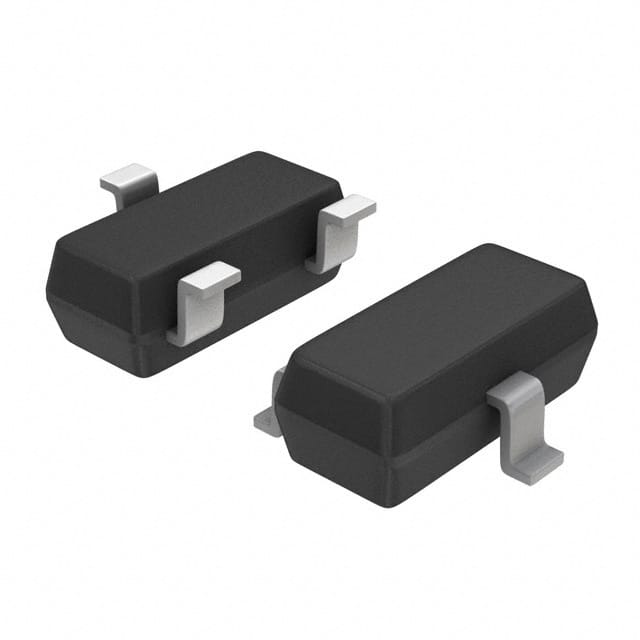
- Package: The MMBFU310LT1 is typically available in a SOT-23 package.
- Essence: Its essence lies in its ability to amplify high-frequency signals with minimal noise interference.
- Packaging/Quantity: It is commonly packaged in reels containing a specific quantity per reel.
Specifications
- Type: N-channel FET
- Maximum Drain-Source Voltage: 25V
- Maximum Continuous Drain Current: 50mA
- Power Dissipation: 225mW
- Operating Temperature Range: -55°C to 150°C
Detailed Pin Configuration
The MMBFU310LT1 features a standard three-pin configuration: 1. Gate (G): Input terminal for controlling the flow of current through the transistor. 2. Drain (D): Output terminal where the amplified signal is obtained. 3. Source (S): Terminal connected to the ground reference.
Functional Features
- High-frequency amplification capabilities
- Low noise performance
- Suitable for RF applications
- Compact SOT-23 package for space-constrained designs
Advantages and Disadvantages
Advantages: - Low noise amplification - High gain at high frequencies - Compact package size
Disadvantages: - Limited maximum voltage and current ratings - Sensitivity to static discharge
Working Principles
The MMBFU310LT1 operates based on the principles of field-effect transistors, where the voltage applied to the gate terminal controls the flow of current between the drain and source terminals. In this case, it is optimized for high-frequency signal amplification with minimal introduction of additional noise.
Detailed Application Field Plans
The MMBFU310LT1 finds application in various RF circuits, including: - Radio frequency amplifiers - Oscillator circuits - RF mixers - Low-noise preamplifiers
Detailed and Complete Alternative Models
- MMBFU310LT1G: Similar specifications and characteristics, offered in a different packaging format.
- MMBFU310LT3G: A variant with enhanced ESD protection and improved thermal performance.
In conclusion, the MMBFU310LT1 serves as a crucial component in RF circuit design, offering high-frequency amplification with low noise characteristics. Its compact package and functional features make it an ideal choice for various RF applications.
Word count: 366
Enumere 10 preguntas y respuestas comunes relacionadas con la aplicación de MMBFU310LT1 en soluciones técnicas
What is MMBFU310LT1?
- MMBFU310LT1 is a low noise, high gain, and high linearity NPN silicon RF transistor designed for use in wireless communication applications.
What are the typical applications of MMBFU310LT1?
- MMBFU310LT1 is commonly used in RF amplifiers, low noise amplifiers (LNAs), and other high-frequency applications in wireless infrastructure, cellular base stations, and small cell systems.
What is the operating frequency range of MMBFU310LT1?
- The operating frequency range of MMBFU310LT1 is typically from 400 MHz to 2700 MHz.
What are the key electrical characteristics of MMBFU310LT1?
- Some key electrical characteristics include a high gain of 15 dB, low noise figure of 0.7 dB, and high linearity with an IP3 of 32 dBm.
What are the thermal considerations for using MMBFU310LT1 in technical solutions?
- It is important to consider proper heat sinking and thermal management to ensure the transistor operates within its specified temperature range for optimal performance and reliability.
Can MMBFU310LT1 be used in battery-powered devices?
- Yes, MMBFU310LT1's low power consumption and high efficiency make it suitable for use in battery-powered devices such as portable radios and wireless sensors.
Are there any recommended biasing configurations for MMBFU310LT1?
- Yes, common biasing configurations include fixed bias, voltage divider bias, and self-bias circuits, which can be selected based on the specific application requirements.
What are the typical input and output matching networks for MMBFU310LT1?
- Typical input and output matching networks may include impedance matching circuits using passive components such as capacitors, inductors, and transmission lines to optimize performance at the desired frequency.
What are the packaging options available for MMBFU310LT1?
- MMBFU310LT1 is available in industry-standard surface mount packages such as SOT-89 and SOT-223, providing flexibility for different PCB layout and assembly requirements.
Are there any design considerations when integrating MMBFU310LT1 into a technical solution?
- Design considerations include RF layout, grounding, decoupling, and proper RF isolation to minimize interference and maintain signal integrity in the overall system design.