

Consulte las especificaciones para obtener detalles del producto.
STGB10NC60KDT4
Product Category
STGB10NC60KDT4 belongs to the category of IGBT (Insulated Gate Bipolar Transistor) modules.
Basic Information Overview
- Use: This IGBT module is commonly used in power electronics applications such as motor drives, inverters, and power supplies.
- Characteristics: It features high switching speed, low on-state voltage drop, and high current capability.
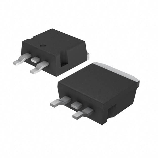
- Package: The STGB10NC60KDT4 comes in a standard module package with insulated metal baseplate (IMB).
- Essence: The essence of this product lies in its ability to efficiently switch high power loads in various electronic systems.
- Packaging/Quantity: Typically, it is packaged individually and sold as a single unit.
Specifications
- Voltage Rating: 600V
- Current Rating: 20A
- Switching Frequency: Up to 20kHz
- Operating Temperature Range: -40°C to 150°C
- Module Type: Single IGBT
Detailed Pin Configuration
The STGB10NC60KDT4 module has a standard pin configuration consisting of gate, collector, and emitter pins. The pinout diagram is as follows:
+---+
Gate  |   |
      +---+
Collector
      +---+
Emitter|
      +---+
Functional Features
- High-speed switching capability
- Low conduction losses
- Overcurrent and overtemperature protection
- Integrated gate resistor for improved EMI performance
Advantages and Disadvantages
Advantages: - Efficient power switching - Reduced power dissipation - Enhanced system reliability - Improved EMI performance
Disadvantages: - Higher cost compared to traditional diode-based solutions - Requires careful thermal management due to high power dissipation
Working Principles
The STGB10NC60KDT4 operates based on the principles of controlling the flow of current through the IGBT by modulating the gate signal. When the gate signal is applied, the IGBT allows current to flow between the collector and emitter, enabling efficient power control in electronic systems.
Detailed Application Field Plans
This IGBT module finds extensive use in various applications including: - Motor drives for electric vehicles - Uninterruptible power supplies (UPS) - Solar inverters - Induction heating systems - Welding equipment
Detailed and Complete Alternative Models
- STGB10NC60KD: Similar specifications but without integrated gate resistor
- STGP10NC60HD: Higher current rating (30A) version for heavier load applications
- STGB12NC60KT4: Higher voltage rating (1200V) for high-voltage applications
In conclusion, the STGB10NC60KDT4 IGBT module offers high-performance power switching capabilities suitable for a wide range of industrial and consumer electronic applications.
Word count: 410
Enumere 10 preguntas y respuestas comunes relacionadas con la aplicación de STGB10NC60KDT4 en soluciones técnicas
What is STGB10NC60KDT4?
- STGB10NC60KDT4 is a 600V, 10A IGBT (Insulated Gate Bipolar Transistor) designed for high power switching applications.
What are the typical applications of STGB10NC60KDT4?
- It is commonly used in motor control, solar inverters, welding equipment, and other industrial applications requiring high power switching.
What are the key features of STGB10NC60KDT4?
- Some key features include low saturation voltage, fast switching speed, and integrated freewheeling diode.
What is the maximum operating temperature of STGB10NC60KDT4?
- The maximum operating temperature is typically around 150°C.
What is the gate-emitter voltage of STGB10NC60KDT4?
- The gate-emitter voltage is usually around ±20V.
Can STGB10NC60KDT4 be used in parallel configurations for higher current applications?
- Yes, it can be used in parallel to increase the current handling capability.
What are the recommended thermal management techniques for STGB10NC60KDT4?
- Proper heat sinking and thermal interface materials are recommended to ensure efficient heat dissipation.
Does STGB10NC60KDT4 require external protection circuitry?
- It is advisable to use external protection circuitry such as overcurrent and overvoltage protection to safeguard the device and the overall system.
What are the typical input and output capacitances of STGB10NC60KDT4?
- The input capacitance is around 2.5nF, and the output capacitance is approximately 2000pF.
Are there any specific PCB layout considerations for using STGB10NC60KDT4?
- It is important to minimize stray inductance and provide proper isolation and clearance distances on the PCB layout to optimize performance and reliability.