

Consulte las especificaciones para obtener detalles del producto.
CD4024BNSR
Product Overview
Category
CD4024BNSR belongs to the category of integrated circuits (ICs).
Use
This IC is commonly used in digital electronics for various applications such as counters, frequency dividers, and shift registers.
Characteristics
- CD4024BNSR is a 14-stage binary ripple counter with an internal oscillator.
- It operates at a wide voltage range of 3V to 18V, making it suitable for different power supply configurations.
- The IC has a low power consumption, making it energy-efficient.
- It offers high noise immunity, ensuring reliable performance even in noisy environments.
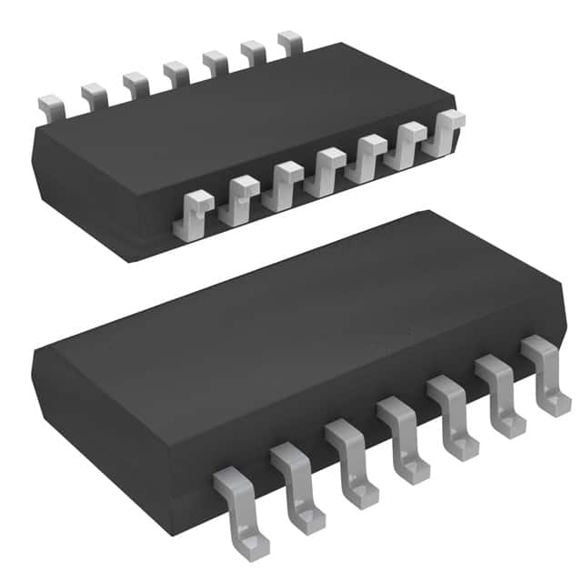
Package
CD4024BNSR is available in a small outline package (SOIC) with 14 pins.
Essence
The essence of CD4024BNSR lies in its ability to count and divide input signals, making it a versatile component in digital circuit design.
Packaging/Quantity
CD4024BNSR is typically packaged in reels or tubes, with each reel containing 2500 units.
Specifications
- Supply Voltage Range: 3V to 18V
- Input Voltage Range: 0V to VDD
- Operating Temperature Range: -55°C to +125°C
- Maximum Clock Frequency: 5 MHz
- Output Current: ±6 mA
Pin Configuration
The detailed pin configuration of CD4024BNSR is as follows:
- Q12
- Q6
- Q5
- Q7
- Q4
- Q3
- Q2
- Q1
- Q0
- MR (Master Reset)
- CP (Clock Pulse)
- GND (Ground)
- VDD (Supply Voltage)
- Q13
Functional Features
- CD4024BNSR can count up to 14 binary stages.
- It has a built-in oscillator that generates clock pulses for counting.
- The Master Reset (MR) pin allows resetting the counter to its initial state.
- The Clock Pulse (CP) pin triggers the counting operation.
- The outputs (Q0-Q13) provide the binary representation of the current count.
Advantages and Disadvantages
Advantages
- Wide operating voltage range allows flexibility in power supply selection.
- Low power consumption makes it suitable for battery-powered applications.
- High noise immunity ensures reliable performance in noisy environments.
- Compact SOIC package enables space-efficient circuit designs.
Disadvantages
- Limited maximum clock frequency may restrict its use in high-speed applications.
- Lack of additional features compared to more advanced counter ICs.
Working Principles
CD4024BNSR operates based on the principle of binary counting. The internal oscillator generates clock pulses, which trigger the counter to increment its count by one. The binary output pins represent the current count in binary form. The Master Reset pin resets the counter to its initial state when activated.
Detailed Application Field Plans
CD4024BNSR finds applications in various fields, including: 1. Digital frequency dividers 2. Event counters 3. Shift registers 4. Industrial automation 5. Consumer electronics
Detailed and Complete Alternative Models
Some alternative models to CD4024BNSR include: 1. CD4020BNSR - 14-stage binary ripple counter without an internal oscillator. 2. CD4017BNSR - Decade counter with 10 decoded outputs. 3. CD4040BNSR - 12-stage binary ripple counter with an internal oscillator.
These alternative models offer different features and specifications, providing options for specific design requirements.
Word Count: 529 words
Enumere 10 preguntas y respuestas comunes relacionadas con la aplicación de CD4024BNSR en soluciones técnicas
Sure! Here are 10 common questions and answers related to the application of CD4024BNSR in technical solutions:
Q: What is CD4024BNSR? A: CD4024BNSR is a 7-stage ripple-carry binary counter/divider IC (integrated circuit) that can be used in various digital applications.
Q: What is the maximum clock frequency supported by CD4024BNSR? A: The maximum clock frequency supported by CD4024BNSR is typically around 8 MHz.
Q: Can CD4024BNSR be used as a frequency divider? A: Yes, CD4024BNSR can be used as a frequency divider by connecting the input clock signal to the CLK pin and using the appropriate output stage.
Q: How many outputs does CD4024BNSR have? A: CD4024BNSR has 7 outputs labeled Q0 to Q6, which represent the binary count values from 0 to 6.
Q: What is the power supply voltage range for CD4024BNSR? A: CD4024BNSR operates with a power supply voltage range of 3V to 18V.
Q: Can CD4024BNSR be cascaded to increase the number of stages? A: Yes, CD4024BNSR can be cascaded by connecting the carry-out (CO) pin of one IC to the clock (CLK) input of the next IC.
Q: What is the typical propagation delay of CD4024BNSR? A: The typical propagation delay of CD4024BNSR is around 60 ns.
Q: Can CD4024BNSR be used in both synchronous and asynchronous applications? A: Yes, CD4024BNSR can be used in both synchronous and asynchronous applications depending on the clock input configuration.
Q: What is the maximum output current that CD4024BNSR can sink/source? A: CD4024BNSR can typically sink or source up to 6 mA of current per output pin.
Q: Can CD4024BNSR be used in battery-powered applications? A: Yes, CD4024BNSR can be used in battery-powered applications as it operates with a wide range of power supply voltages and has low power consumption.
Please note that these answers are general and may vary based on specific datasheet specifications and application requirements.