

Consulte las especificaciones para obtener detalles del producto.
SN74AC564DBR
Product Overview
- Category: Integrated Circuit (IC)
- Use: Digital Logic
- Characteristics: Octal D-Type Flip-Flop with 3-State Outputs
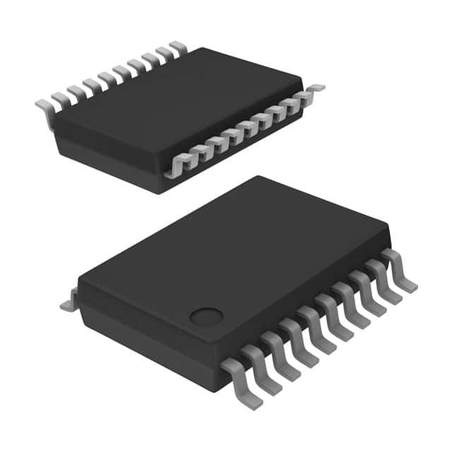
- Package: SSOP (Shrink Small Outline Package)
- Essence: High-speed, low-power consumption flip-flop
- Packaging/Quantity: Tape and Reel, 2500 pieces per reel
Specifications
- Supply Voltage Range: 2 V to 6 V
- Input Voltage Range: 0 V to VCC
- Output Voltage Range: 0 V to VCC
- Operating Temperature Range: -40°C to +85°C
- Propagation Delay Time: 4.5 ns (typical)
- Output Drive Capability: ±24 mA
Detailed Pin Configuration
The SN74AC564DBR has a total of 20 pins. The pin configuration is as follows:
- GND (Ground)
- D0 (Data Input 0)
- D1 (Data Input 1)
- D2 (Data Input 2)
- D3 (Data Input 3)
- D4 (Data Input 4)
- D5 (Data Input 5)
- D6 (Data Input 6)
- D7 (Data Input 7)
- CP (Clock Pulse Input)
- MR (Master Reset Input)
- OE (Output Enable Input)
- Q0 (Flip-Flop Output 0)
- Q1 (Flip-Flop Output 1)
- Q2 (Flip-Flop Output 2)
- Q3 (Flip-Flop Output 3)
- Q4 (Flip-Flop Output 4)
- Q5 (Flip-Flop Output 5)
- Q6 (Flip-Flop Output 6)
- Q7 (Flip-Flop Output 7)
Functional Features
- Octal D-Type Flip-Flop with 3-State Outputs
- Positive-Edge Triggered
- Buffered Inputs and Outputs
- Common Clock and Master Reset
- Output Enable Control
Advantages and Disadvantages
Advantages: - High-speed operation - Low-power consumption - Compact SSOP package for space-saving designs - Buffered inputs and outputs for improved signal integrity - 3-state outputs allow multiple devices to share a common bus
Disadvantages: - Limited supply voltage range (2 V to 6 V) - Propagation delay time may not be suitable for ultra-high-speed applications
Working Principles
The SN74AC564DBR is an octal D-type flip-flop with 3-state outputs. It operates on positive-edge triggering, meaning the flip-flops' outputs change state when a rising edge is detected on the clock pulse input (CP). The master reset input (MR) allows all flip-flop outputs to be asynchronously reset to a low state. The output enable input (OE) controls the 3-state outputs, enabling or disabling their functionality.
Detailed Application Field Plans
The SN74AC564DBR is commonly used in various digital logic applications, including but not limited to:
- Data storage and transfer systems
- Address decoding circuits
- Register banks
- Memory modules
- Bus interface units
Its high-speed operation, low-power consumption, and compact package make it suitable for applications where space and power efficiency are crucial.
Detailed and Complete Alternative Models
- SN74AC574: Octal D-Type Flip-Flop with 3-State Outputs, similar functionality but different pin configuration.
- SN74HC564: Octal D-Type Flip-Flop with 3-State Outputs, compatible with a wider supply voltage range (2 V to 6 V).
- SN74LS564: Octal D-Type Flip-Flop with 3-State Outputs, compatible with a wider operating temperature range (-55°C to +125°C).
These alternative models offer similar functionality to the SN74AC564DBR but may have different specifications or pin configurations to suit specific application requirements.
Word count: 430 words
Enumere 10 preguntas y respuestas comunes relacionadas con la aplicación de SN74AC564DBR en soluciones técnicas
Sure! Here are 10 common questions and answers related to the application of SN74AC564DBR:
Q: What is SN74AC564DBR? A: SN74AC564DBR is a specific type of integrated circuit (IC) known as a flip-flop, which is commonly used in digital electronics.
Q: What is the purpose of SN74AC564DBR? A: The purpose of SN74AC564DBR is to store and manipulate binary data in digital systems. It can be used for various applications such as data storage, synchronization, and control.
Q: What is the voltage range supported by SN74AC564DBR? A: SN74AC564DBR supports a voltage range of 2V to 6V, making it compatible with a wide range of digital systems.
Q: How many flip-flops are there in SN74AC564DBR? A: SN74AC564DBR consists of 8 individual flip-flops, each capable of storing one bit of data.
Q: What is the clock input in SN74AC564DBR used for? A: The clock input is used to control the timing of data storage and retrieval operations in SN74AC564DBR. It determines when the flip-flops update their stored values.
Q: Can SN74AC564DBR be used for synchronous or asynchronous operation? A: SN74AC564DBR can be used for both synchronous and asynchronous operation, depending on how the clock input is utilized.
Q: What is the maximum operating frequency of SN74AC564DBR? A: The maximum operating frequency of SN74AC564DBR is typically around 100 MHz, but it may vary depending on the specific conditions and setup.
Q: What is the power supply requirement for SN74AC564DBR? A: SN74AC564DBR requires a single power supply voltage of 2V to 6V, making it easy to integrate into various digital systems.
Q: Can SN74AC564DBR be cascaded or daisy-chained with other flip-flops? A: Yes, SN74AC564DBR can be cascaded or daisy-chained with other flip-flops to create larger storage registers or shift registers.
Q: Are there any special considerations for using SN74AC564DBR in high-speed applications? A: In high-speed applications, it is important to consider signal integrity, proper decoupling, and noise reduction techniques to ensure reliable operation of SN74AC564DBR.
Please note that these answers are general and may vary depending on the specific requirements and application of SN74AC564DBR in a technical solution.