

Consulte las especificaciones para obtener detalles del producto.
UCC2813PWTR-2G4
Product Overview
Category
UCC2813PWTR-2G4 belongs to the category of integrated circuits (ICs).
Use
This product is commonly used in power management applications.
Characteristics
- Integrated circuit
- Power management functionality
- High efficiency
- Compact size
- Low power consumption
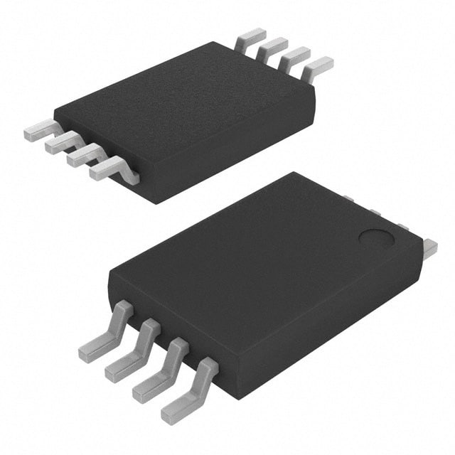
Package
UCC2813PWTR-2G4 is available in a small outline package (SOP) with a thermal pad for improved heat dissipation.
Essence
The essence of UCC2813PWTR-2G4 lies in its ability to efficiently manage power in various electronic devices.
Packaging/Quantity
This product is typically packaged in reels, containing a specific quantity of ICs per reel. The exact quantity may vary depending on the manufacturer's specifications.
Specifications
- Input voltage range: 2.7V to 18V
- Output voltage range: 0.8V to 16V
- Maximum output current: 500mA
- Operating temperature range: -40°C to 125°C
- Switching frequency: 100kHz to 1MHz
- Control method: Current mode control
- Protection features: Overvoltage protection, undervoltage lockout, overcurrent protection
Pin Configuration
UCC2813PWTR-2G4 has the following pin configuration:
- VREF: Reference voltage input
- COMP: Error amplifier output
- FB: Feedback voltage input
- CS: Current sense input
- GND: Ground
- RT/CT: Timing resistor/capacitor connection
- VCC: Supply voltage input
- OUT: Power output
Functional Features
- Current mode control for stable and efficient power management
- Error amplifier for precise regulation
- Overvoltage protection to safeguard connected devices
- Undervoltage lockout for reliable operation
- Overcurrent protection to prevent damage
Advantages and Disadvantages
Advantages
- High efficiency leads to reduced power consumption
- Compact size allows for integration in space-constrained designs
- Wide input and output voltage ranges provide versatility
- Protection features enhance reliability and safety
Disadvantages
- Limited maximum output current may not be suitable for high-power applications
- Requires additional external components for complete functionality
Working Principles
UCC2813PWTR-2G4 operates based on the current mode control principle. It regulates the output voltage by adjusting the duty cycle of the internal power switch. The error amplifier compares the feedback voltage with the reference voltage, generating an error signal that controls the power switch. This feedback loop ensures stable and accurate voltage regulation.
Detailed Application Field Plans
UCC2813PWTR-2G4 finds application in various power management scenarios, including but not limited to: - Switching power supplies - Battery chargers - LED drivers - DC-DC converters - Industrial control systems
Detailed and Complete Alternative Models
Some alternative models that offer similar functionality to UCC2813PWTR-2G4 include: - LM2576-ADJ - LT1073 - MC34063A - TPS5430
These alternatives can be considered based on specific requirements and design constraints.
In conclusion, UCC2813PWTR-2G4 is a versatile integrated circuit used for efficient power management in various electronic devices. Its compact size, high efficiency, and protection features make it suitable for a wide range of applications. However, its limited maximum output current and requirement for additional external components should be taken into consideration during design.
Enumere 10 preguntas y respuestas comunes relacionadas con la aplicación de UCC2813PWTR-2G4 en soluciones técnicas
Sure! Here are 10 common questions and answers related to the application of UCC2813PWTR-2G4 in technical solutions:
Q: What is UCC2813PWTR-2G4? A: UCC2813PWTR-2G4 is a pulse width modulation (PWM) controller IC used for controlling power supply circuits.
Q: What are the key features of UCC2813PWTR-2G4? A: Some key features include adjustable frequency, soft-start capability, cycle-by-cycle current limiting, and overvoltage protection.
Q: How can UCC2813PWTR-2G4 be used in power supply applications? A: It can be used to regulate the output voltage of a power supply by controlling the duty cycle of the PWM signal.
Q: What is the maximum operating frequency of UCC2813PWTR-2G4? A: The maximum operating frequency is typically around 500 kHz.
Q: Can UCC2813PWTR-2G4 handle high input voltages? A: Yes, it can handle input voltages up to 30V.
Q: Does UCC2813PWTR-2G4 have built-in protection features? A: Yes, it has built-in protection features such as overvoltage protection and cycle-by-cycle current limiting.
Q: Can UCC2813PWTR-2G4 be used in both buck and boost converter topologies? A: Yes, it can be used in both buck and boost converter topologies.
Q: Is UCC2813PWTR-2G4 suitable for low-power applications? A: Yes, it is suitable for low-power applications as it has a low quiescent current and can operate in pulse skipping mode.
Q: What is the typical output voltage range of UCC2813PWTR-2G4? A: The typical output voltage range is between 1.25V and 30V.
Q: Are there any application notes or reference designs available for UCC2813PWTR-2G4? A: Yes, Texas Instruments provides application notes and reference designs that can help with the implementation of UCC2813PWTR-2G4 in various power supply applications.
Please note that the answers provided here are general and may vary depending on specific design requirements and datasheet specifications.