

Consulte las especificaciones para obtener detalles del producto.
SUM60N10-17-E3
Introduction
The SUM60N10-17-E3 is a power MOSFET belonging to the category of electronic components. This device is widely used in various applications due to its unique characteristics and functional features.
Basic Information Overview
- Category: Power MOSFET
- Use: The SUM60N10-17-E3 is used as a switching device in power supply, motor control, and other high-current applications.
- Characteristics: It exhibits low on-state resistance, high switching speed, and low gate charge, making it suitable for high-efficiency power conversion.
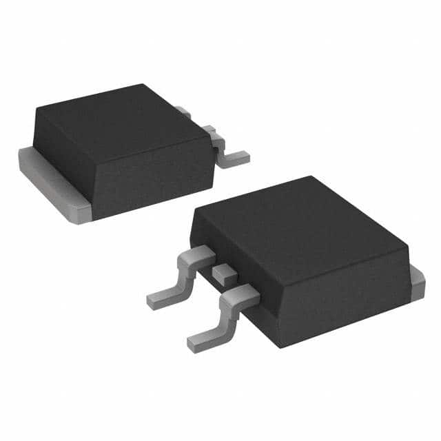
- Package: The SUM60N10-17-E3 is typically available in a TO-263 package.
- Essence: Its essence lies in providing efficient power switching capabilities in electronic circuits.
- Packaging/Quantity: It is commonly packaged in reels containing a specific quantity based on manufacturer specifications.
Specifications
The detailed specifications of the SUM60N10-17-E3 include: - Drain-Source Voltage (VDS): 100V - Continuous Drain Current (ID): 60A - On-State Resistance (RDS(on)): 17mΩ - Gate-Source Voltage (VGS): ±20V - Total Gate Charge (Qg): 50nC - Operating Temperature Range: -55°C to 175°C
Detailed Pin Configuration
The pin configuration of the SUM60N10-17-E3 is as follows: - Pin 1: Gate (G) - Pin 2: Drain (D) - Pin 3: Source (S)
Functional Features
The functional features of the SUM60N10-17-E3 include: - Low on-state resistance for minimal power dissipation - High switching speed for efficient operation - Low gate charge for reduced drive requirements
Advantages and Disadvantages
Advantages
- High efficiency in power conversion applications
- Suitable for high-current circuits
- Fast switching capability
Disadvantages
- May require careful consideration of driving circuitry
- Sensitive to overvoltage conditions
Working Principles
The SUM60N10-17-E3 operates based on the principles of field-effect transistors, where the application of a voltage at the gate terminal controls the flow of current between the drain and source terminals.
Detailed Application Field Plans
The SUM60N10-17-E3 finds extensive use in the following application fields: - Switch-mode power supplies - Motor control systems - Inverters and converters for renewable energy systems - Automotive electronics
Detailed and Complete Alternative Models
Some alternative models to the SUM60N10-17-E3 include: - IRF3205 - FDP8878 - STP80NF70
In conclusion, the SUM60N10-17-E3 power MOSFET offers high-performance characteristics and versatile applications in various electronic circuits, making it a valuable component in modern electronic designs.
Word Count: 411
Enumere 10 preguntas y respuestas comunes relacionadas con la aplicación de SUM60N10-17-E3 en soluciones técnicas
What is the maximum drain-source voltage for SUM60N10-17-E3?
- The maximum drain-source voltage for SUM60N10-17-E3 is 100V.
What is the continuous drain current rating of SUM60N10-17-E3?
- The continuous drain current rating of SUM60N10-17-E3 is 60A.
What is the on-state resistance (RDS(on)) of SUM60N10-17-E3?
- The on-state resistance (RDS(on)) of SUM60N10-17-E3 is typically 0.017 ohms.
Can SUM60N10-17-E3 be used in high-power applications?
- Yes, SUM60N10-17-E3 is suitable for high-power applications due to its high current and voltage ratings.
What are the typical applications for SUM60N10-17-E3?
- Typical applications for SUM60N10-17-E3 include power supplies, motor control, and automotive systems.
Does SUM60N10-17-E3 require a heat sink for operation?
- Depending on the specific application and operating conditions, a heat sink may be recommended for optimal performance of SUM60N10-17-E3.
What is the gate threshold voltage of SUM60N10-17-E3?
- The gate threshold voltage of SUM60N10-17-E3 is typically around 2.5V.
Is SUM60N10-17-E3 suitable for switching applications?
- Yes, SUM60N10-17-E3 is well-suited for switching applications due to its low on-state resistance and high current handling capability.
What is the maximum junction temperature for SUM60N10-17-E3?
- The maximum junction temperature for SUM60N10-17-E3 is 175°C.
Are there any recommended driver circuits for controlling SUM60N10-17-E3?
- Various MOSFET driver circuits are compatible with SUM60N10-17-E3, and the choice depends on the specific requirements of the application.